Check out the Teaser video for our new HW project.
Web: www.cycleat.com
Facebook: www.facebook.com/cycleat
Thursday, June 12, 2014

Tuesday, April 29, 2014
Setting up the Coin BLE Dev Kit
The following instructions are for setting up a brand new Coin BLE Dev Board for easy programming with the Arduino IDE and Bluetooth integration. Even though the original boards sold out and Coin did not plan on doing another manufacturing run, many people were still interested in getting their hands on these boards. Because of this, our team took over the second manufacturing run so that everyone who wants the board can get one.
To purchase your own Coin BLE Dev Board (NO LONGER AVAILABLE), visit http://coindev2.myshopify.com/
The boards come assembled fresh from the factory, so this post documents the steps that must be followed to get your board programming ready.
The original Coin BLE Wiki can be found at https://github.com/CoinApps/arduino-ble-dev-kit/wiki
To Program the BLE module:
- For default BLE behavior (send 1 byte at a time from the Arduino via Bluetooth) or if you do not want to write any custom code for the BLE module, program the out1-19-NOV-2013.hex file provided on the Coin Wiki (Git Hub Link to code)
- Follow the instructions to program the BLE module here: Coin Wiki for BLE Software Instructions
To Program the Bootloader on the Arduino
2 Methods:
- Using the Atmel mkII AVRISP Programmer
- Using another Arduino and the Arduino IDE
Method 1: Atmel mkII AVRISP Programmer
Requirements:
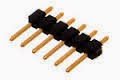
- 6 pin 0.1" male-to-male header
- Jumper wires

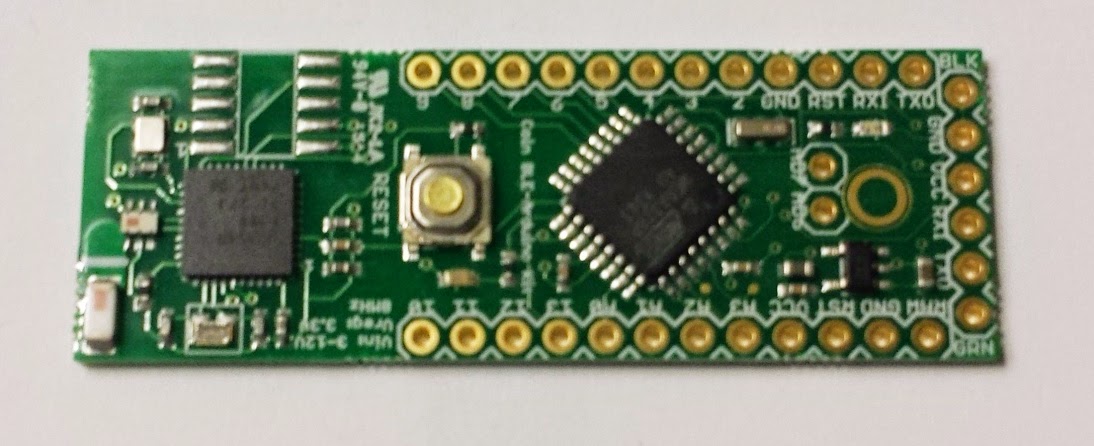
- Coin BLE Dev Board
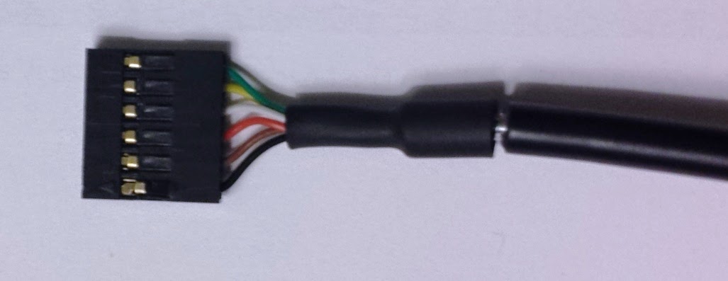
- FTDI Programming Cable
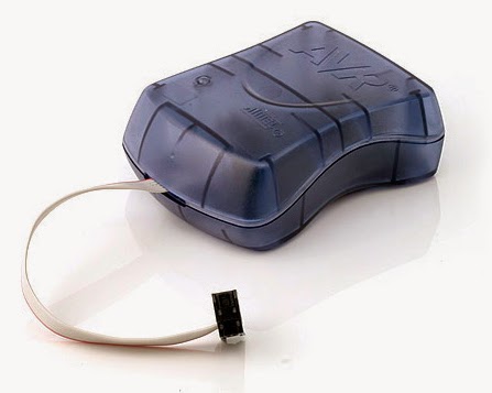
- Atmel mkII AVRISP Programmer (~$37.00)
- Atmel Studio 6 or Atmel Studio 6 Programmer Standalone (free software, download link here)
- Jumper wires
Instructions:
1) Place 6 pin header into the FTDI cable
2) Wire the following pins up to the mkII programmer (no need to solder them in, just bend to ensure pin contact)

 |
| ***Taken from http://www.avrfreaks.net/index.php?name=PNphpBB2&file=printview&t=81538 *** |
3) Place FTDI cable into dev board for powering the board (the red light will be on). Make sure you orient the FTDI cable correctly when you connect it (the board says GRN on the side that corresponds to the green wire on the FTDI cable)

4) Open up Atmel Studio 6: Tools >> Device Programming
5) When the programming window pops up, set up the following properties
- Tool: Select AVRISP mkII
- Device: ATA6614Q
6) Click Apply
7) IMPORTANT: Under the Interface Settings tab, set the ISP Clock to 125kHz (for the first time this must be done since the fuse settings haven't been set yet)
8) Under the Memories tab, browse for the ATmegaBOOT_168_atmega328_pro_8MHz.hex bootloader (under most normal Windows installs, this will be located under C:\Program Files (x86)\Arduino\hardware\arduino\bootloaders\atmega\)

9) Click Program
10) Upon success, go the the Fuses tab and set the fuses to the following:
- EXTENDED: 0xFD
- HIGH: 0XDA
- LOW: 0XFF

11) Click Program
12) Now verify that the bootloader was properly loaded by opening up the Arduino IDE and loading the "Blink.ino" file onto the dev board using the FTDI cable only as the following describes:
- Select the proper serial port where your FTDI programming cable is plugged into
- Under Board, select Arduino Pro or Pro Mini (3.3V, 8MHz) w/ATmega328


Method 2: Use another Arduino as a AVRISP programmer
The second method is to use another Arduino to program the bootloader. This can be done with the setup seen below, except for replacing the top Arduino with the dev kit board. Modified from http://arduino.cc/en/Tutorial/ArduinoToBreadboard.
If you have a new ATmega328 (or ATmega168), you'll need to burn the bootloader onto it. You can do this using an Arduino board as an in-system program (ISP). If the microcontroller already has the bootloader on it (e.g. because you took it out of an Arduino board or ordered an already-bootloadedATmega), you can skip this section.
To burn the bootloader, follow these steps:
- Upload the ArduinoISP sketch onto your Arduino board that you will be burning the bootloader from (You'll need to select the board and serial port from the Tools menu that correspond to your board.) This can be found in the Arduino IDE at File >> Examples >> ArduinoISP. Upload this sketch to the device.
- Wire up the Arduino board and microcontroller as shown below. The 4 yellow wires in the image from the programmer Arduino should instead be contacted with the following pins on the dev board (once again, just make sure you have contacts on the pins using the jumper wires rather than soldering them completely in if you want to save some time):
- PIN 13 on programmer Arduino <--> PIN 13 on dev board
- PIN 12 on programmer Arduino <--> PIN 12 on dev board
- PIN 11 on programmer Arduino <--> PIN 11 on dev board
- PIN 10 on programmer Arduino <--> RST on dev board

**Taken from http://arduino.cc/en/Tutorial/ArduinoISP**
- Select "Arduino Pro or Pro Mini (3.3V, 8MHz)w/ATmega328" from the Tools > Board menu (see below ):
- PIN 13 on programmer Arduino <--> PIN 13 on dev board
- PIN 12 on programmer Arduino <--> PIN 12 on dev board
- PIN 11 on programmer Arduino <--> PIN 11 on dev board
- PIN 10 on programmer Arduino <--> RST on dev board
|
| **Taken from http://arduino.cc/en/Tutorial/ArduinoISP** |
- Run Tools > Burn Bootloader > w/ Arduino as ISP.

- Finally, select Burn Bootloader from the Tools menu to burn the bootloader onto the board.
Now verify that the bootloader was properly loaded by opening up the Arduino IDE and loading the "Blink.ino" file onto the dev board using the FTDI cable only.
Now verify that the bootloader was properly loaded by opening up the Arduino IDE and loading the "Blink.ino" file onto the dev board using the FTDI cable only.
You should only need to burn the bootloader once. After you've done so, you can remove the jumper wires connected to pins 10, 11, 12, and 13 of the Arduino board.
- Connect the FTDI programmer to the dev board (see above steps on how to do this)
- Select the proper serial port where your FTDI programming cable is plugged into
- IMPORTANT: Under Board, select Arduino Pro or Pro Mini (3.3V, 8MHz) w/ATmega328
- Click Upload Sketch button in the IDE
More info on using Arduino as AVRISP bootload burner:
- The Arduino setup page for this can be found here: http://arduino.cc/en/Tutorial/ArduinoToBreadboard
- Another reference: http://www.instructables.com/id/Turn-Your-Arduino-Into-an-ISP/
Program the Arduino with the Example Programs from the Coin Wiki
- Download the example code seen here from the Wiki
- Load the code onto the Arduino in the same manner as you did the "Blink.ino" above
Thursday, January 17, 2013
Breakout with accelerometer glove
Project Overview
This project required the integration of at least one continuous input sensor with an interactive game as well as requiring the gamer to "tag" in using an NFC card reader. Our team, Ross Yeager and Ryan Rho, used 1 accelerometer, 1 sport glove, 2 Arduinos, and the Adafruit NFC card breakout board to implement the old arcade game, Breakout, as well as a plotting utility to graph the accelerometer data and visualize gesture recognitions. For our continuous sensing, the accelerometer was used (it is embedded into a glove worn by the player):
-If the player rolls his hand to the left or right, it corresponds to continuous movement left or right in the game for as long as it remains rolled. -A quick upward flick in the Z-axis direction corresponds to a discrete "power" in the game (extending the bar at bottom momentarily).
Image: Device

Images: How to Use the Controller


Utility Tool
Utility Visualizer (X,Y,Z Axes)
The utility was created to visualize the accelerometer data and to show when the selected gestures occurred. The first three plots are the X,Y,and Z axes respectively. The utility was done using the Processing IDE, and the gesture recognition was based on a threshold state machine. Thresholds were determined experimentally, and future improvements of the utility would include user ability to control/adjust thresholds. The right left FSM consisted of the following states:
-NOLR: This state no left or right motion occurs
-LEFT: To get in this state, the threshold must have been crossed downwards and it must remain below the threshold to stay in this state. This state continuously outputs a valid "left" signal and this is visualized in the utility.
-RIGHT: To get in this state, the threshold must have been crossed upwards and it must remain above the threshold to stay in this state. This state continuously outputs a valid "right" signal and this is visualized in the utility.
-LLEFT: Leaves the "left" state. Has an upward crossing of the threshold. Indicates end of left hand rotation gesture.
-LRIGHT: Leaves the "right" state. Has an downward crossing of the threshold. Indicates end of left hand rotation gesture.
The flick motion is detected by looking for an upward crossing of the z-axis threshold. Since it is discrete it only occurs once per gesture (as opposed to left right signals which the user can hold).
Finally a summation plot of all of the axes is at the very bottom of the utility.
Gesture recognition was represented visually in the utility by a shade of magenta/purple.

Utility Video
ARDUINO
Arduino 1: Accelerometer
For the accelerometer, the baud rate is set to 9600 and the accelerometer was wired up to the first 3 analog pins. A2D readings are taken ever loop and sent serially to the host computer in the following format:
Utility Visualizer (X,Y,Z Axes)
The utility was created to visualize the accelerometer data and to show when the selected gestures occurred. The first three plots are the X,Y,and Z axes respectively. The utility was done using the Processing IDE, and the gesture recognition was based on a threshold state machine. Thresholds were determined experimentally, and future improvements of the utility would include user ability to control/adjust thresholds. The right left FSM consisted of the following states:
-NOLR: This state no left or right motion occurs
-LEFT: To get in this state, the threshold must have been crossed downwards and it must remain below the threshold to stay in this state. This state continuously outputs a valid "left" signal and this is visualized in the utility.
-RIGHT: To get in this state, the threshold must have been crossed upwards and it must remain above the threshold to stay in this state. This state continuously outputs a valid "right" signal and this is visualized in the utility.
-LLEFT: Leaves the "left" state. Has an upward crossing of the threshold. Indicates end of left hand rotation gesture.
-LRIGHT: Leaves the "right" state. Has an downward crossing of the threshold. Indicates end of left hand rotation gesture.
The flick motion is detected by looking for an upward crossing of the z-axis threshold. Since it is discrete it only occurs once per gesture (as opposed to left right signals which the user can hold).
Finally a summation plot of all of the axes is at the very bottom of the utility.
Gesture recognition was represented visually in the utility by a shade of magenta/purple.

Utility Video
ARDUINO
Arduino 1: Accelerometer
For the accelerometer, the baud rate is set to 9600 and the accelerometer was wired up to the first 3 analog pins. A2D readings are taken ever loop and sent serially to the host computer in the following format:
"###|###|###\n"
where the numbers are the X-axis, second Y-axis, and Z-axis readings.
Arduino 2: NFC ID
For the second Arduino, the NFC ID breakout board is connected to it using the built in SPI input pins. The baud rate is 9600 and the nfc object is initiated. Using the Adafruit library, when a user swipes his ID the tag is identified and the total score and high score are sent serially as a string to the host computer. If the game is over and the host computer wants to send a new high score to write onto the card, the serial interrupt occurs and the Arduino writes the incoming data to the card instead of reading from it.
We used the classic arcade game, Breakout, for our project game. We used Pygame, a game library for Python. As the basis, we modified a sample game source code in Pygame to suit our project needs and to integrate the sensor and RFID applications into the game. The left and right rotation gestures correspond to left and right movement of the bar, and the upward flick extends the bar to cover more ground momentarily. Points are scored from destroying all of the bricks in the game, and the game is over when the player misses the ball too many times.
where the numbers are the X-axis, second Y-axis, and Z-axis readings.
Arduino 2: NFC ID
For the second Arduino, the NFC ID breakout board is connected to it using the built in SPI input pins. The baud rate is 9600 and the nfc object is initiated. Using the Adafruit library, when a user swipes his ID the tag is identified and the total score and high score are sent serially as a string to the host computer. If the game is over and the host computer wants to send a new high score to write onto the card, the serial interrupt occurs and the Arduino writes the incoming data to the card instead of reading from it.
Software
Game: BREAKOUTWe used the classic arcade game, Breakout, for our project game. We used Pygame, a game library for Python. As the basis, we modified a sample game source code in Pygame to suit our project needs and to integrate the sensor and RFID applications into the game. The left and right rotation gestures correspond to left and right movement of the bar, and the upward flick extends the bar to cover more ground momentarily. Points are scored from destroying all of the bricks in the game, and the game is over when the player misses the ball too many times.
Sunday, September 9, 2012
This Here is a home work assignment over the weekend that I had for my device interface class here at UC Berkeley. The task was to create a simple keyboard using Arduino and additional HW. I decided to use a 5-key (direction pad) keyboard that displays the letter selected on the computer screen.
In general, this is a fairly simple task; however, because I wanted to have the computer GUI that talked to the Arduino it made the difficulty level a little harder.

For the first part, I just used an actual keyboard up, down, left, right arrows and enter to control the Processing GUI. I will then convert the keyboard input to serial input from the Arduino but it should look very similar. Here is the initial Processing Code:
//Variables
static final int enterh = 30;
PFont f;
int i, charSelect, col;
color fillUP, fillDOWN, fillLEFT, fillRIGHT, fillENTER;
String words;
String[] keyboard = {"a", "b", "c", "d", "e",
"f", "g", "h", "i", "j", "k",
"l", "m", "n", "o", "p", "q",
"r", "s", "t", "u", "v", "w",
"x", "y", "z", "space"};
//Setup Loop
void setup() {
size(400, 360);
words = "";
charSelect = 0;
col = 0;
background(1);
// Create the font
f = createFont("Ethnocentric", 20);
i=0;
background(0);
}
//Draw loop
void draw() {
background(0);
textAlign(LEFT);
textFont(f,9);
fill(255);
text("a b c d e f g h i j k l m", width/2-4*enterh, height/4);
text("n o p q r s t u v w x y z", width/2-4*enterh, height/4+16);
text("space", width/2-4*enterh, height/4+32);
textFont(f, 30);
strokeWeight(1);
stroke(255, 255, 255);
rectMode(CENTER);
fill(0);
//rect(width/2,40, 90, 40);
rectMode(CORNER);
fill(255, 0, 0);
textAlign(CENTER);
text(keyboard[charSelect], width/2, 50);
strokeWeight(4);
stroke(15, 242, 39);
fill(0);
rect(width/2-4*enterh, height/2-1.5*enterh,enterh*8, enterh*4);
stroke(237, 255, 3);
fill(fillENTER);
rect((width/2)-enterh, height/2, enterh*2, enterh);
fill(fillLEFT);
triangle((width/2)-enterh*1.66, height*.5, (width/2)-enterh*1.66, height*.5+enterh,(width/2)-(enterh*2.5), height*.5+(enterh/2));
fill(fillRIGHT);
triangle((width/2)+enterh*1.66, height*.5, (width/2)+enterh*1.66, height*.5+enterh,(width/2)+(enterh*2.5), height*.5+(enterh/2));
fill(fillUP);
triangle((width/2)-enterh, height*.5-enterh*.333, (width/2)+enterh, height*.5-enterh*.33,(width/2), height*.5-enterh);
fill(fillDOWN);
triangle((width/2)-enterh, height*.5+enterh*1.333, (width/2)+enterh, height*.5+enterh*1.33,(width/2), height*.5+enterh*2);
delay(200);
fillUP = color(0, 0, 0);
fillDOWN = color(0, 0, 0);
fillLEFT = color(0, 0, 0);
fillRIGHT = color(0, 0, 0);
fillENTER = color(0, 0, 0);
textAlign(CENTER);
textFont(f, 16);
fill(237, 255, 3);
text(words, width/2, height*.9);
//println(words);
}
void keyPressed() {
if (key == CODED)
{
if (keyCode == UP)
{
fillUP = color(255, 0, 0);
if(col>0)
col -= 1;
else
col = 2;
if(col == 2)
charSelect = 26;
else{
charSelect -= 13;
}
}
else if (keyCode == DOWN)
{
fillDOWN = color(255, 0, 0);
if(col <2)
col += 1;
else
col = 0;
if(col == 2)
charSelect = 26;
else if(col == 0)
charSelect = 0;
else
charSelect += 13;
}
else if(keyCode == LEFT)
{
fillLEFT= color(255, 0, 0);
if(charSelect>0)
charSelect--;
else
charSelect = keyboard.length-1;
}
else if(keyCode == RIGHT)
{
fillRIGHT= color(255, 0, 0);
if(charSelect<keyboard.length-1)
charSelect++;
else
charSelect = 0;
}
}
else if(key == ENTER)
{
fillENTER = color(255, 0, 0);
if(keyboard[charSelect] == "space")
words = words + " ";
else
words = words + keyboard[charSelect];
}
else
{
fillUP = color(0, 0, 0);
fillDOWN = color(0, 0, 0);
fillLEFT = color(0, 0, 0);
fillRIGHT = color(0, 0, 0);
fillENTER = color(0, 0, 0);
}
if(charSelect < 13)
col = 0;
else if(charSelect <26)
col = 1;
else
col = 2;
println(col + " " + charSelect);
}
In general, this is a fairly simple task; however, because I wanted to have the computer GUI that talked to the Arduino it made the difficulty level a little harder.
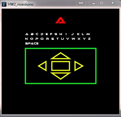
For the first part, I just used an actual keyboard up, down, left, right arrows and enter to control the Processing GUI. I will then convert the keyboard input to serial input from the Arduino but it should look very similar. Here is the initial Processing Code:
//Variables
static final int enterh = 30;
PFont f;
int i, charSelect, col;
color fillUP, fillDOWN, fillLEFT, fillRIGHT, fillENTER;
String words;
String[] keyboard = {"a", "b", "c", "d", "e",
"f", "g", "h", "i", "j", "k",
"l", "m", "n", "o", "p", "q",
"r", "s", "t", "u", "v", "w",
"x", "y", "z", "space"};
//Setup Loop
void setup() {
size(400, 360);
words = "";
charSelect = 0;
col = 0;
background(1);
// Create the font
f = createFont("Ethnocentric", 20);
i=0;
background(0);
}
//Draw loop
void draw() {
background(0);
textAlign(LEFT);
textFont(f,9);
fill(255);
text("a b c d e f g h i j k l m", width/2-4*enterh, height/4);
text("n o p q r s t u v w x y z", width/2-4*enterh, height/4+16);
text("space", width/2-4*enterh, height/4+32);
textFont(f, 30);
strokeWeight(1);
stroke(255, 255, 255);
rectMode(CENTER);
fill(0);
//rect(width/2,40, 90, 40);
rectMode(CORNER);
fill(255, 0, 0);
textAlign(CENTER);
text(keyboard[charSelect], width/2, 50);
strokeWeight(4);
stroke(15, 242, 39);
fill(0);
rect(width/2-4*enterh, height/2-1.5*enterh,enterh*8, enterh*4);
stroke(237, 255, 3);
fill(fillENTER);
rect((width/2)-enterh, height/2, enterh*2, enterh);
fill(fillLEFT);
triangle((width/2)-enterh*1.66, height*.5, (width/2)-enterh*1.66, height*.5+enterh,(width/2)-(enterh*2.5), height*.5+(enterh/2));
fill(fillRIGHT);
triangle((width/2)+enterh*1.66, height*.5, (width/2)+enterh*1.66, height*.5+enterh,(width/2)+(enterh*2.5), height*.5+(enterh/2));
fill(fillUP);
triangle((width/2)-enterh, height*.5-enterh*.333, (width/2)+enterh, height*.5-enterh*.33,(width/2), height*.5-enterh);
fill(fillDOWN);
triangle((width/2)-enterh, height*.5+enterh*1.333, (width/2)+enterh, height*.5+enterh*1.33,(width/2), height*.5+enterh*2);
delay(200);
fillUP = color(0, 0, 0);
fillDOWN = color(0, 0, 0);
fillLEFT = color(0, 0, 0);
fillRIGHT = color(0, 0, 0);
fillENTER = color(0, 0, 0);
textAlign(CENTER);
textFont(f, 16);
fill(237, 255, 3);
text(words, width/2, height*.9);
//println(words);
}
void keyPressed() {
if (key == CODED)
{
if (keyCode == UP)
{
fillUP = color(255, 0, 0);
if(col>0)
col -= 1;
else
col = 2;
if(col == 2)
charSelect = 26;
else{
charSelect -= 13;
}
}
else if (keyCode == DOWN)
{
fillDOWN = color(255, 0, 0);
if(col <2)
col += 1;
else
col = 0;
if(col == 2)
charSelect = 26;
else if(col == 0)
charSelect = 0;
else
charSelect += 13;
}
else if(keyCode == LEFT)
{
fillLEFT= color(255, 0, 0);
if(charSelect>0)
charSelect--;
else
charSelect = keyboard.length-1;
}
else if(keyCode == RIGHT)
{
fillRIGHT= color(255, 0, 0);
if(charSelect<keyboard.length-1)
charSelect++;
else
charSelect = 0;
}
}
else if(key == ENTER)
{
fillENTER = color(255, 0, 0);
if(keyboard[charSelect] == "space")
words = words + " ";
else
words = words + keyboard[charSelect];
}
else
{
fillUP = color(0, 0, 0);
fillDOWN = color(0, 0, 0);
fillLEFT = color(0, 0, 0);
fillRIGHT = color(0, 0, 0);
fillENTER = color(0, 0, 0);
}
if(charSelect < 13)
col = 0;
else if(charSelect <26)
col = 1;
else
col = 2;
println(col + " " + charSelect);
}
Processing is best used with Arduino for receiving serial data. Here is a Processing example for a simple read over the serial port.
A simple way to test the serial with just your computer is to get 2 USB->Serial connections (RS232), a serial cable and connect them together (USB/Serial-->SerialCable-->Serial/USB) and then you can output and read serial information. This may help in testing Processing code if an Arduino is not available (as is in my case; waiting for it to arrive, but have an assignment due before then!) Here is a simple serial read on Processing.
A simple way to test the serial with just your computer is to get 2 USB->Serial connections (RS232), a serial cable and connect them together (USB/Serial-->SerialCable-->Serial/USB) and then you can output and read serial information. This may help in testing Processing code if an Arduino is not available (as is in my case; waiting for it to arrive, but have an assignment due before then!) Here is a simple serial read on Processing.
| Name | read() |
|---|---|
| Examples | // Example by Tom Igoe
import processing.serial.*;
Serial myPort; // The serial port
void setup() {
// List all the available serial ports
println(Serial.list());
// Open the port you are using at the rate you want:
myPort = new Serial(this, Serial.list()[0], 9600);
}
void draw() {
while (myPort.available() > 0) {
int inByte = myPort.read();
println(inByte);
}
}
|
Interacting an Arduino with Processing
Processing is an easy-to-learn language for writing graphics programs based on Java.
You don't have to use Processing in this assignment, but you can.
The basic model to do this is as follows (I'll start with the simple unidirectional case where you are only sending data into Processing):
* You write Arduino code that sends data to an attached PC using the serial port functions.
* You write Processing code that opens the appropriate serial port on the PC and reads the data that your Arduino program sent; it then parses the data and responds appropriately.
* You have to come up with a protocol for your messages so Arduino and Processing agree on the format of the messages. This can be as simple as "send a single number followed by the newline character" and as complex as sending XML or JSON.
This is flexible, but also a lot of work: you have to define the protocol and write two pieces of code. Debugging these setups is also time consuming. In many cases, you only need to read simple analog or digital input pins, and write to output pins.
For this common case, Processing provides a library that consists of 1) A Processing library (called "Arduino") and 2) a special firmware (aka sketch) that you run on your Arduino board (called "Firmata"). Firmata exposes a simple, efficient protocol for reading and writing to pins. The Processing library then creates a wrapper around that protocol with Processing/Java functions that mimc the names of Arduino/C functions.
More information is here: http://www.arduino.cc/playground/Interfacing/Processing
You don't have to use Processing in this assignment, but you can.
The basic model to do this is as follows (I'll start with the simple unidirectional case where you are only sending data into Processing):
* You write Arduino code that sends data to an attached PC using the serial port functions.
* You write Processing code that opens the appropriate serial port on the PC and reads the data that your Arduino program sent; it then parses the data and responds appropriately.
* You have to come up with a protocol for your messages so Arduino and Processing agree on the format of the messages. This can be as simple as "send a single number followed by the newline character" and as complex as sending XML or JSON.
This is flexible, but also a lot of work: you have to define the protocol and write two pieces of code. Debugging these setups is also time consuming. In many cases, you only need to read simple analog or digital input pins, and write to output pins.
For this common case, Processing provides a library that consists of 1) A Processing library (called "Arduino") and 2) a special firmware (aka sketch) that you run on your Arduino board (called "Firmata"). Firmata exposes a simple, efficient protocol for reading and writing to pins. The Processing library then creates a wrapper around that protocol with Processing/Java functions that mimc the names of Arduino/C functions.
More information is here: http://www.arduino.cc/playground/Interfacing/Processing
Sunday, June 12, 2011
Using Code On a PC to Interact with the Arduino
Writing firmware to operate a microcontroller such as the Arduino can provide the user with an array of power at his disposal, but the processing power and further interaction is limited due to the nature of the microcontroller itself (its a MICROcontroller aka not an Intel processor). With this in mind, I was interested in interacting with the Arduino on my PC. At first I thought I would have to do this in C using Visual Studio and the Windows library (to talk to the COMM PORTS); however, I found another open source compiler from the creators of the Arduino sketchbook called Processing:
 "Processing is an open source programming language and environment for people who want to create images, animations, and interactions. Initially developed to serve as a software sketchbook and to teach fundamentals of computer programming within a visual context, Processing also has evolved into a tool for generating finished professional work. Today, there are tens of thousands of students, artists, designers, researchers, and hobbyists who use Processing for learning, prototyping, and production"
 "Processing is an open source programming language and environment for people who want to create images, animations, and interactions. Initially developed to serve as a software sketchbook and to teach fundamentals of computer programming within a visual context, Processing also has evolved into a tool for generating finished professional work. Today, there are tens of thousands of students, artists, designers, researchers, and hobbyists who use Processing for learning, prototyping, and production"
 -www.processing.org
Here's the simple setup for downloading Processing and setting it up for Arduino interaction:
- Download the processing zip file from http://processing.org/download/
- Extract this file
- Download the Arduino Processing library at: http://arduino.cc/playground/uploads/Nilseuropa/processing-arduinomega.zip
- Extract this file
- Create a folder in your Processing folder called "libraries"; the Processing folder is most likely loaded in your My Documents (not to be confused with the processing zip file that you just downloaded)
- Copy the Arduino folder from the extracted file into the Processing folder
- Open up the Processing sketchbook, click Sketch->Import Library and you should see an Arduino library at the bottom of the list
- You are good to go! Just include the Arduino library and the Serial library anytime you use Processing to interact with the Arduino. Examples can be found on the Processing website and on the Arduino website (www.arduino.cc)
For my next project I am going to use an infrared sensor to detect motion and use the Arduino and Bluetooth to wirelessly report whenever the motion detector goes off using the Processing sketchbook.
Subscribe to:
Posts (Atom)